Introduction
Clarity’s new easy-to-deploy External Power System provides reliable, continuous power for a Clarity Node when connected with Accessory Modules with high power requirements, such as the Ozone, and Black Carbon Modules. When fully charged, the Battery Pack can power a typical Node and power-hungry Module deployment for two weeks with no sunlight on the solar panel.
IMPORTANT:
- The External Power System is large and heavy. It may require two people to install, and professional equipment such as a bucket truck.
- The External Power System user is responsible for proper installation and for the safety of the deployment.
- Please review this entire deployment guide for detailed instructions on deploying your External Power System, which has been designed to work specifically with the Clarity Node-S.
- The small Node-mounted solar panel is not used and may be removed when using the External Power System.
- Please note that the battery is shipped with a low State Of Charge (SOC) of typically <30% as per safety regulations. Ideally, the solar installation should be assembled and the battery charged by the solar panel for a few days before deploying sensor nodes and modules. If this is not possible at the deployment site, the panel can be attached to the battery and left out in full sun before deployment.
- It is advised to set up and test together all of the equipment (node, accessory modules, the solar panel, and battery pack) before taking everything out to the final deployment site. Please see the appropriate Node and Module Deployment Guides in our Knowledge Base for more information.
In the Boxes
Typically, these components will arrive in 3 separate boxes (panel bracket, solar panel, battery pack), but they may be packaged or bundled differently depending on shipping requirements.
|
One (1) Weatherproof Battery Pack 60Ah with attached mounting hardware |
|
|
One (1) Pre-assembled Solar Panel Mounting Bracket with:
|
|
|
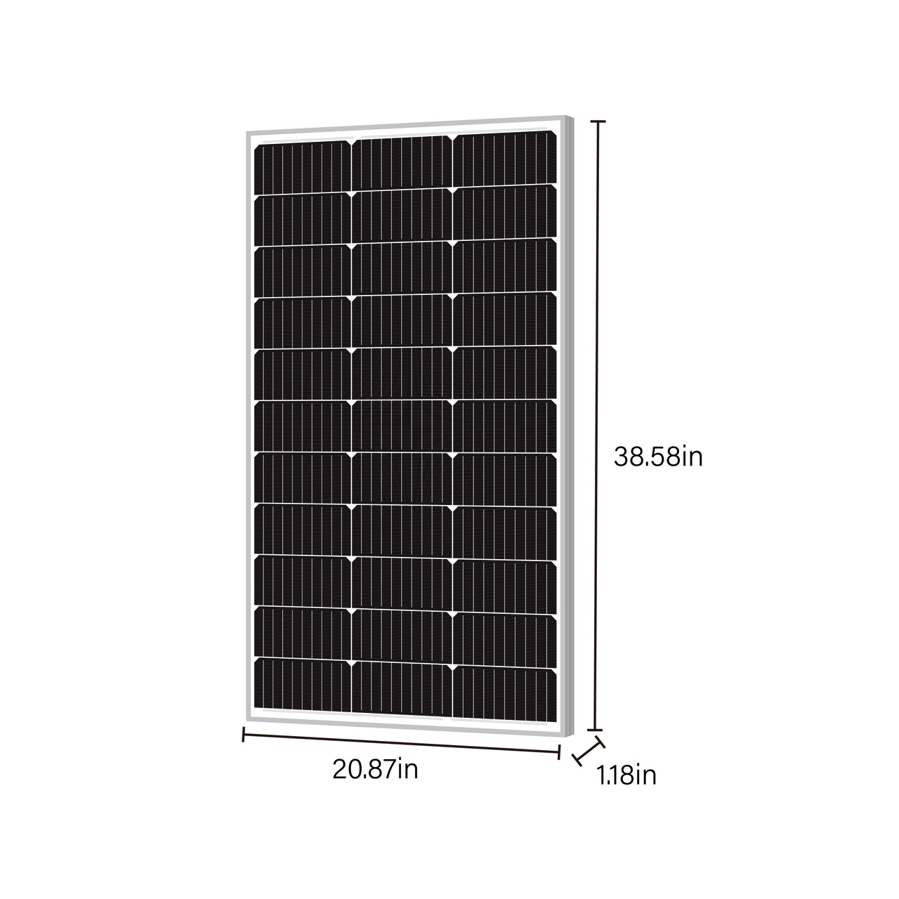
One (1) 100W Monocrystalline Solar Panel with:
|
|
|
One (1) Battery Pack to Node Power Cable, 2m long |
|
|
Assembly Tool Kit:
|
You will also need the following equipment (not included):
- Adjustable wrench
- A medium-sized Phillips head screwdriver
- Stainless steel zip ties, hose clamps, or screws for mounting that are appropriate for your site(s)
Choose Panel Orientation
Typically, a panel will need to see at least a couple of hours of full sun each day to keep the battery sufficiently charged; nonetheless, more is generally better to add to operating margins. Correct solar panel placement and orientation is important to achieve reliable year-round operation.
Before deciding on the exact location and mounting angle for the solar panel:
- Consider the general mounting area and surrounding objects that might shade the panel throughout the day (trees, buildings, etc.) and the general level of sunlight available.
- Consult the orientation guidelines below as well as online tools such as this Peak Sun Hours Calculator (with Map)
- When possible, plan for mounting Node and Modules where they will be shaded by the solar panel during the hotter times of the day. Although each Node and Module comes with their own solar radiation shield, this extra shading can help reduce sensor errors in extreme conditions.
Panel Tilt Angle

- The optimal tilt angle for year-round maximum power is generally similar to the degree of latitude of the location. For best winter performance in lower-light locations, add 15 degrees of tilt.
- For very high-latitude and thus low sun angle locations, you may wish to get more sophisticated about panel angles to ensure maximum system charge during winter months and bad weather conditions, if so please consult the following online reference: Solar Panel Tilt Angle Calculator
- Panel Angle for Snow Country: Since a snow-covered panel will produce no electricity, in areas that have significant snow accumulation it is wise to select a panel angle of at least 45 degrees, if not steeper, so that gravity can help keep the panel unobstructed. This angle will be a compromise depending on available sunlight in the wintertime. At deployment sites that have easier access by project personnel, a lower angle can still be used if the panel is regularly swept off with any small broom or clean rag after significant snow accumulation.
Panel Azimuth Direction
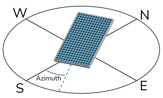
The panel surface should generally be pointed towards the equator. In other words, the panel should be oriented to the south if in the northern hemisphere and to the north if in the southern hemisphere. In locations with less solar exposure, you may wish to get more sophisticated about panel azimuth direction, if so please consult the following online reference: Solar Panel Azimuth Angle Calculator
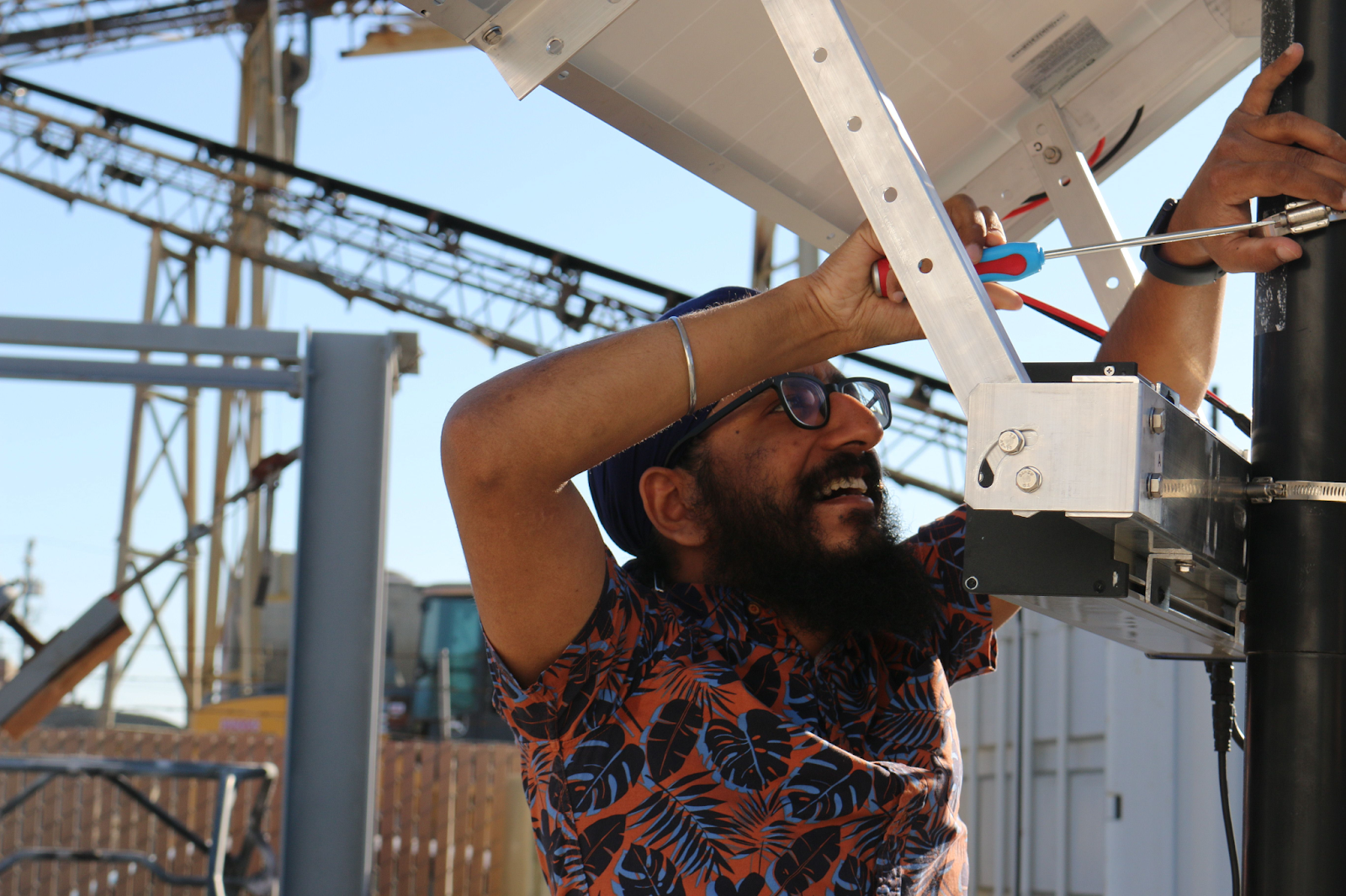
Install Solar Panel and Bracket
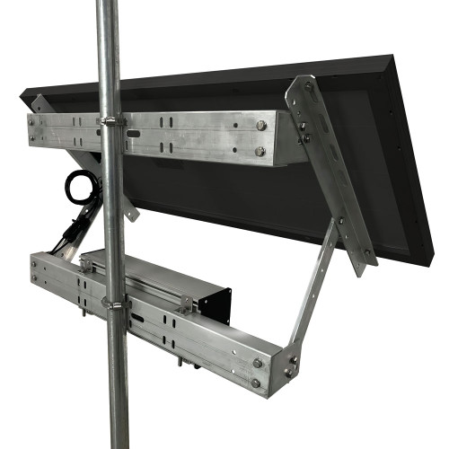
This photograph shows a proper solar panel bracket installation using the horizontal battery pack mounting option. The bracket is pre-assembled out of the box, but you will need to adjust the mounting arms to your particular needs, and tighten the fasteners to keep it in position.
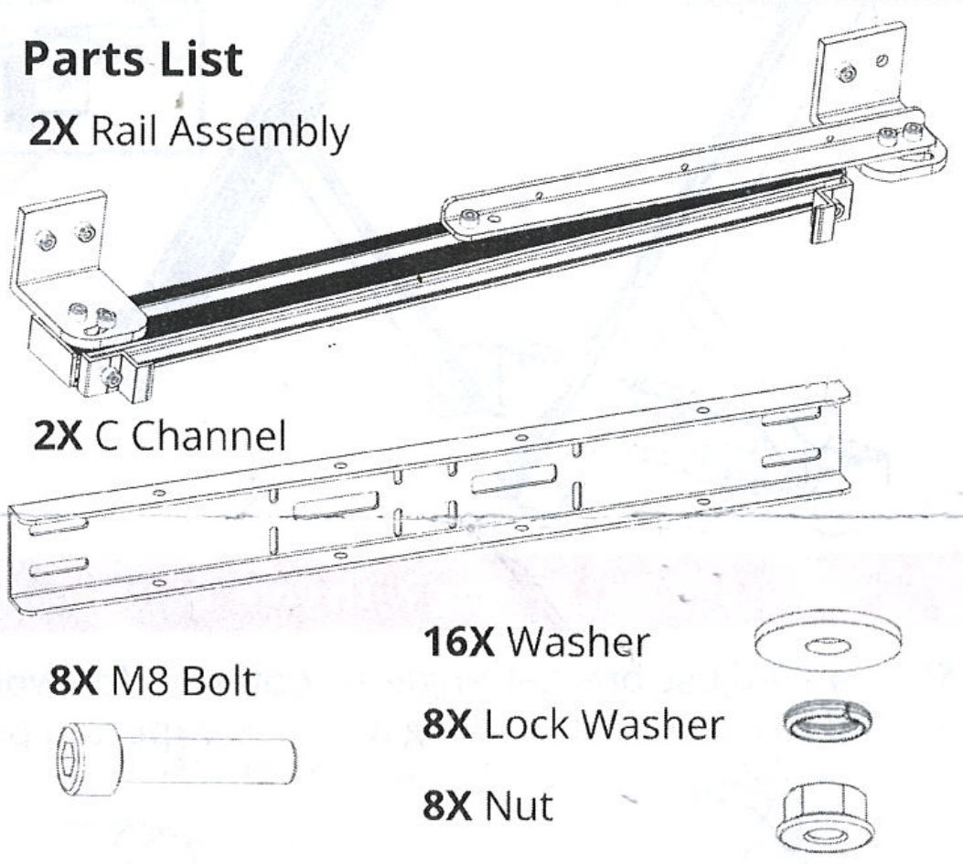
Start by mounting the bracket to the pole or other structure, using the instructions found in the box which are duplicated here for your convenience.
- Adjust the rail assemblies so that they can stand on a flat surface. You can adjust the angle later. Rails should be facing inward

- Connect two (2) C channels to the rail assemblies with eight (8) bolts. Tighten.
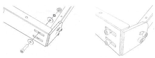
- Test fit solar panel on assembled bracket by placing panel under Z-clamps

- Adjust bracket angle to optimize solar panel tilt angle by moving or adjusting supports and record this angle for tracking actual vs expected performance - see Panel Tilt Angle paragraph above. Tighten and secure all bolts.

- Remove the solar panel prior to mounting the bracket on a pole or other structure. Mount bracket bracket with four (4) steel straps. Point due South (North in Southern hemisphere) - see Panel Azimuth Direction paragraph above.

- Re-attach the solar panel under Z-clamps and tighten Z-clamps.

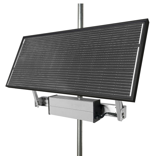
Install Battery Pack
The battery pack may be mounted either horizontally on the solar mounting bracket as shown in the above photo, or vertically directly onto a pole or other structure.
- Determining factors are potential wind load, weight distribution, as well as other unique mounting restrictions and limitations.
- Also, it ideally should be in shade from the direct sun as much as possible, either underneath the solar panel or on the back side of a light pole, etc.
Horizontal Battery Option

Vertical Battery Option
If this orientation is used, be sure to place the connector panel pointing down towards the ground to help protect it from rain.

Connect Node and Solar Panel to Battery Pack
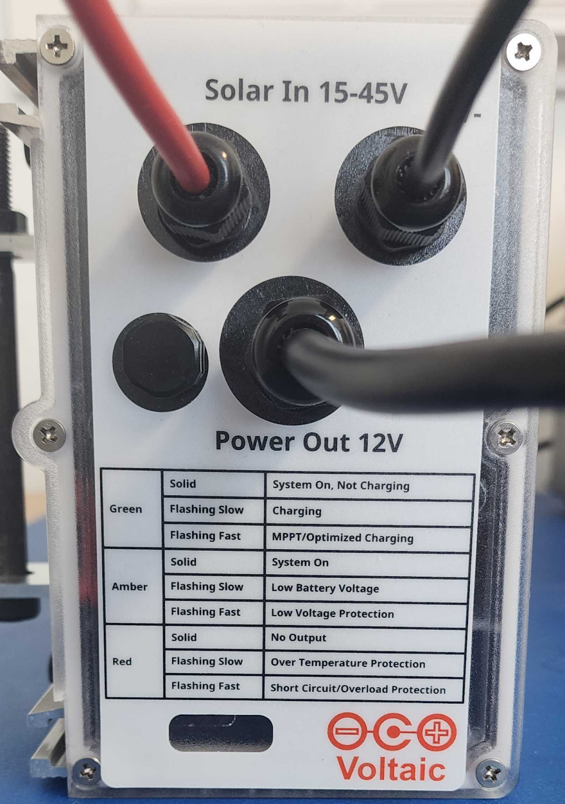
About the Battery Pack
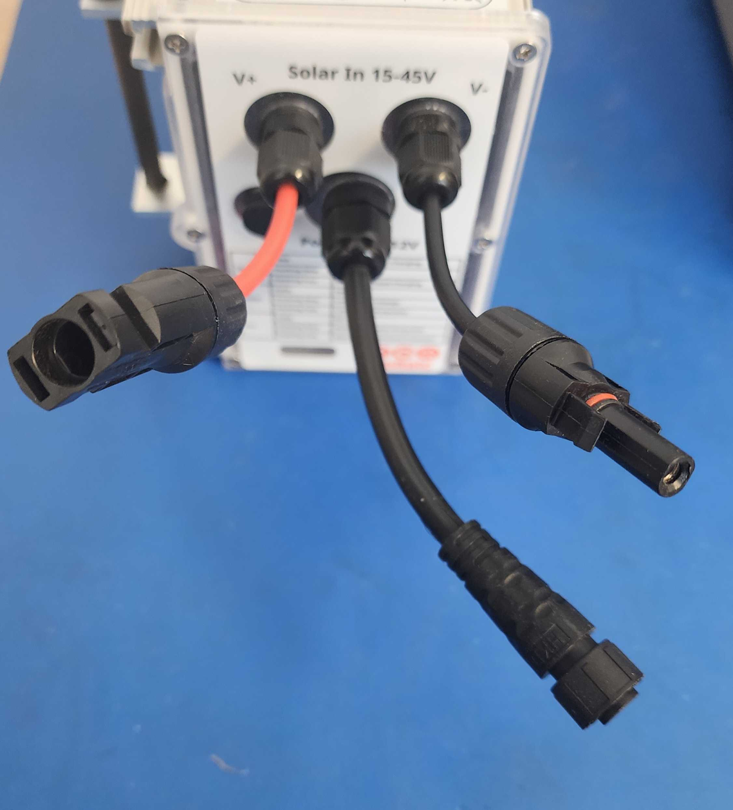
Battery Pack Connectors layout
Power output cable is in the middle, solar panel inputs are on the sides, with red wire being positive and black indicating negative.
Battery Pack Status Lights
The charge controller status lights are visible through the front of the battery pack. They can provide helpful information about whether the system is receiving power from solar panels, providing power to a device, and other systems faults.
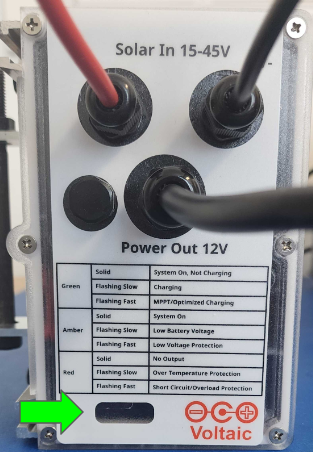
Note: a Node power cable needs to be connected to the Battery Pack power output to turn the system on and also to enable battery charging from the solar panel.
|
LED Color/Function |
LED Rate |
Indication |
GREEN Charge Status |
Solid |
System On, Not Charging |
|
Flashing Slow |
Charging |
|
|
Flashing Fast |
MPPT/Fast Charging |
|
AMBER Output Status |
Solid |
System On |
|
Flashing Slow |
Low Battery Voltage |
|
|
Flashing Fast |
Low Voltage Protection |
|
RED Output Error |
Solid |
No Output |
|
Flashing Slow |
Over Temperature |
|
|
Flashing Fast |
Short Circuit Protection |
Connect Node to Battery Pack Power Output
This step turns on the Battery Pack’s charge controller. The orange light should turn on. Note that a cable needs to be connected to the power output to turn the system on and also for the solar panel to charge the battery.
Connect Solar Panel to Battery Pack Power Input
- Connect the solar panel output to the Battery Pack input MC4-style connectors by pushing them into each other until the retainer clips latch into place, which also makes the connection weather-tight. These connectors are polarized so that it’s impossible to connect them backwards.
- To remove a connection, push on the retainer clips with fingertips or some needle nose pliers while pulling the two contacts apart.
Secure Wires
Cables should be secured so they do not move in the wind. Bundle wires together neatly and zip tie to the brackets using plastic zip ties only, metal zip ties here can cut through the wire’s insulation. Use drip loops where needed to help rainwater drip off the cable before it runs further down into a connector.
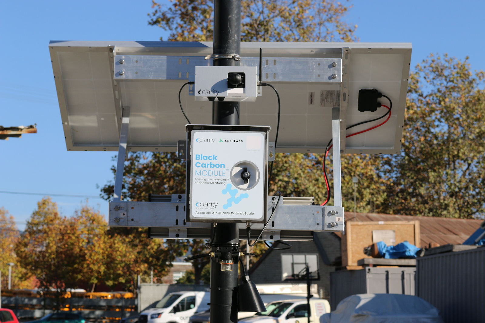
Clarity Node-S and Black Carbon Module successfully deployed with the External Power System.
Maintaining your Clarity External Power System
Preventive Maintenance
The entire External Power System is designed for a long, trouble-free lifetime. Clarity recommends a regular 3-month preventive maintenance schedule to keep the solar panel clean and to ensure reliable mounting and connections. When possible, you should:
- Remove any leaves, dirt, bird droppings, and other grime and debris that can reduce solar panel output by wiping down the solar panel with a clean damp cloth. Cleaning agents are generally not required, but if needed for tough cases, any mild commercial glass cleaner product can be used.
- Check the cable connections for finger tightness at the node and module connector(s), the node antenna, and solar panel connections. These can come loose over time due to wind-induced vibrations, so make sure everything is still weathertight. Also make sure that cables are still tied down securely and not flopping around in the wind.
- Check all mechanical mounting devices and fasteners, which also can vibrate loose over time. Is everything still solidly mounted and ready to battle the elements? Good! If not, fix it before it becomes a bigger problem. Give special attention to the large and heavy solar panel and battery pack.
Reliability and Repair
The Battery Pack is rated for 2000 full charge/discharge cycles, and the solar panel has a 10-year rated lifetime, while typical use in a Clarity deployment should last even longer. If for some reason your External Power System is not operating as expected now or in the future, please contact support@clarity.io.
Please take a note or photo of the serial number on your Battery Pack for future reference, as indicated on the label as shown in the photo below. It will be useful if you need assistance.
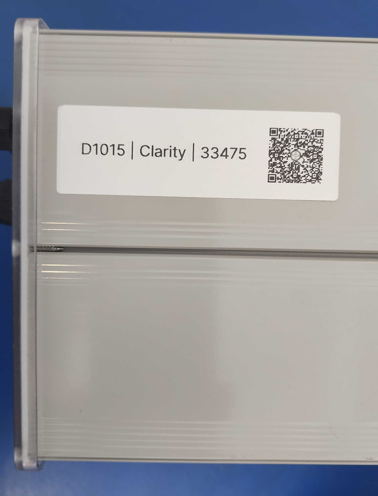
To get expert help resolving questions about or problems with this product, please contact us at support@clarity.io.