IMPORTANT:
- ⚠️ Every time the Black Carbon Module is power cycled, the Filter Tape Cartridge is advanced by one spot. Please minimize the number of power cycles to minimize tape waste.
- You must first configure the Clarity Node-S device before connecting the Black Carbon Module. If you have not yet configured the Node-S, please find instructions here.
- The Black Carbon Module requires the Clarity Node-S operate on external power. Therefore, the small Node-mounted solar panel is not used and may be removed when using the Clarity Node-S with the Black Carbon module.
- An optional Clarity External Power System (EPS) may be used to power the node and any attached modules, including the Black Carbon Module.
- Please review this entire guide for more detailed instructions for your module as it has been designed to work specifically with the Clarity Node-S.
- If you desire more detailed information about the module’s internal AethLabs MA350 Black Carbon micro-aethalometer and the data it produces, please refer to the User Manual.
- However, the MA350 has been modified to work effectively on the Clarity platform, so please use this guide and Clarity support as the final authority and DO NOT make any menu selections or parameter adjustments other than detailed in this Deployment Guide without express and detailed instructions from the Clarity support team. Doing so can result in system malfunction and possibly equipment damage.

In the box
|
1 (one) Black Carbon Module with mounting hardware:
|
 |
| 1 (one) Accessory Module to Node cable, 8 conductor, M12 Male-Male, 2m long | 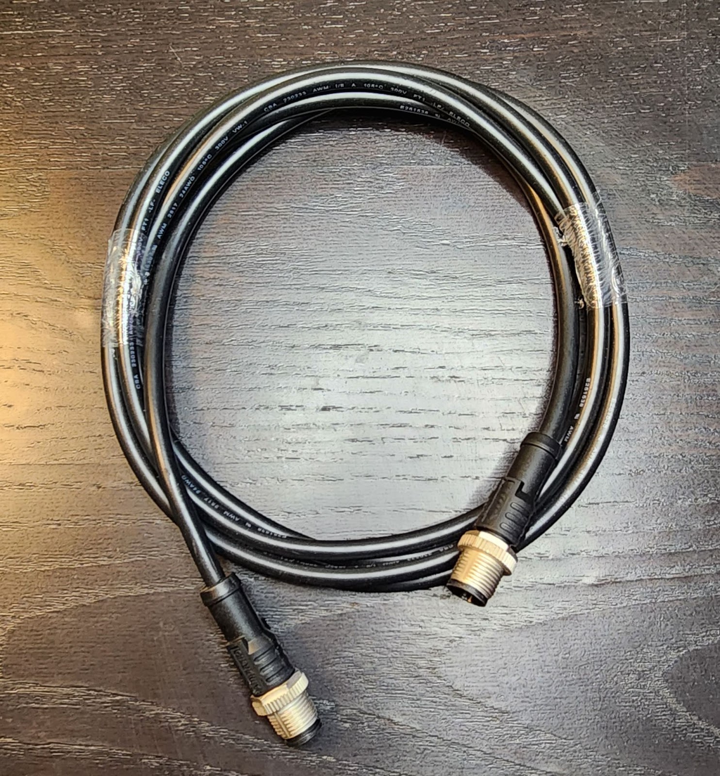 |
|
2 (two) Filter Tape Cartridges (one is already installed in the Module) |
 |
|
1 (one) Inlet Protection Kit |
 |
For Black Carbon Module deployment, you will also need the following equipment (not included):
- A medium-sized Phillips head screwdriver
- Stainless steel zip ties, hose clamps, or screws for mounting that are appropriate for your site(s)
When preparing deployment hardware, please refer to the Black Carbon Module mounting interface dimensions found in the deployment section below.
Pair the Module to a compatible Node-S on Dashboard
To use an accessory Module, it needs to be paired with a Node-S device. The pairing process tells the Clarity Cloud that the two are connected, correctly configures the Node-S and allows the Module to begin sending data to the Clarity Cloud.
- Before beginning your module pairing, make sure your Node-S is configured. To do that please review the instructions for configuring your node here
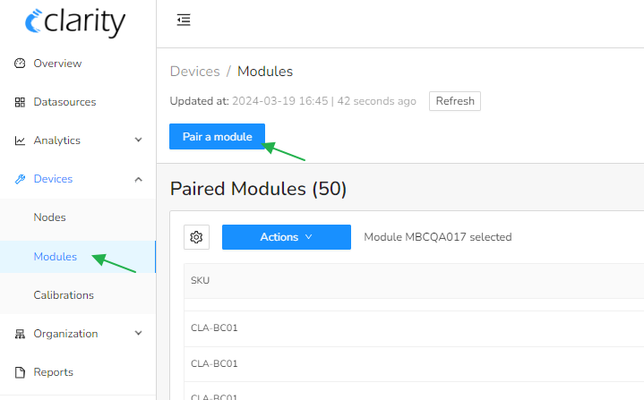
- Sign into your Clarity Dashboard and navigate to “Devices / Modules”
- Click on “Pair a Module”. A configuration stepper will open.
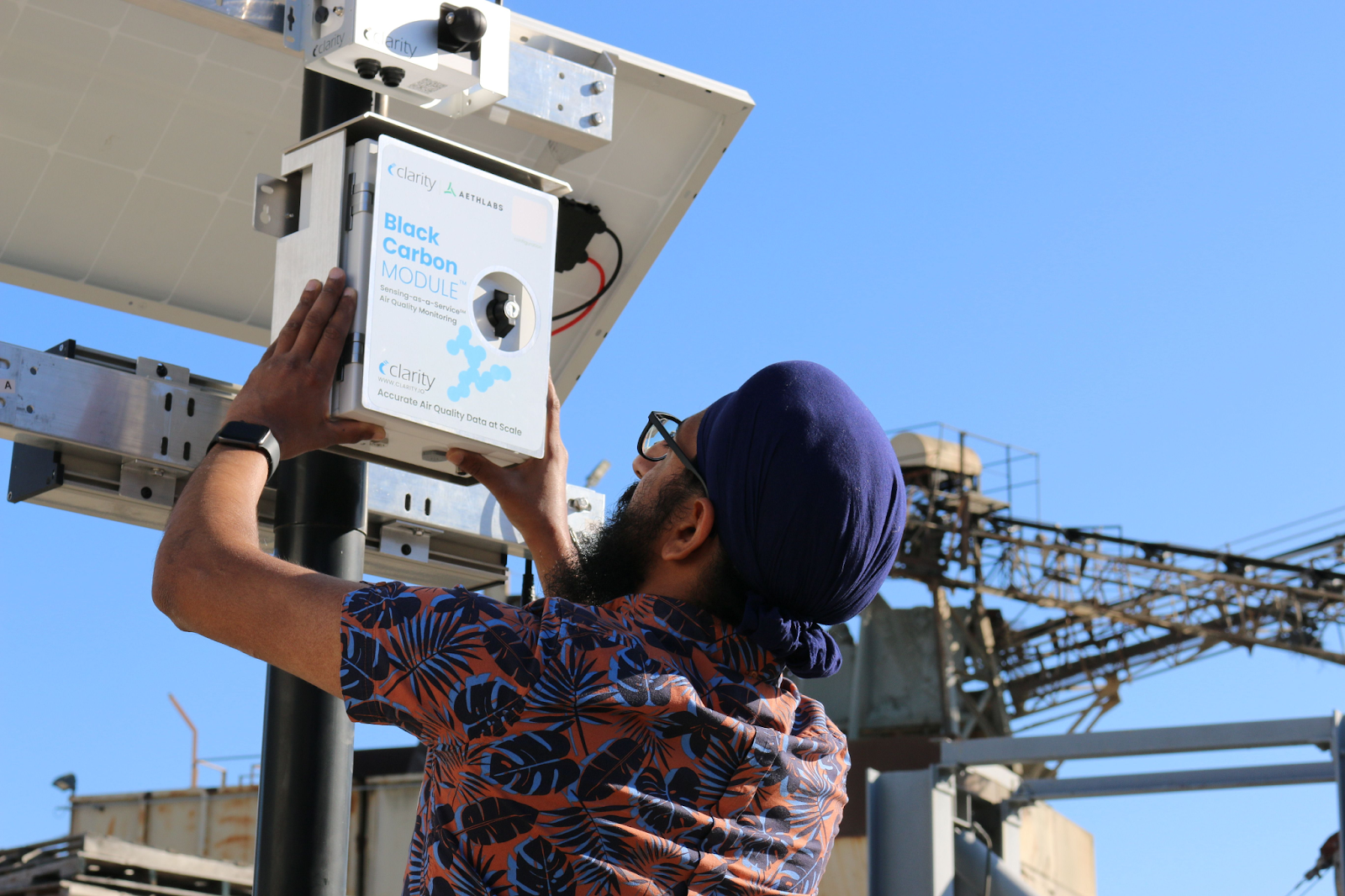
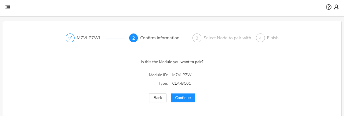
- Input the module ID, select the correct ID from the dropdown, or scan the module QR code. Click “Next Step”.
See
- See the image below for the module ID location.
- See the image below for the module ID location.
- Confirm the information on the screen matches what is found on the module ID sticker. Confirm both the Module ID and Model are correct.
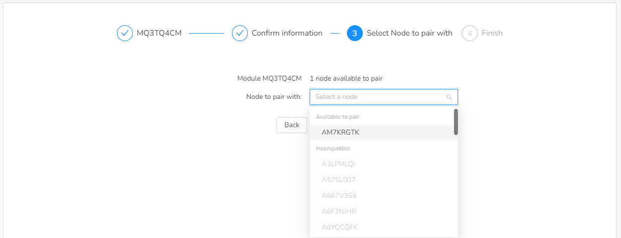
- Input the ID of the Node-S device that you want to pair the module with, or select the ID from the drop down menu. The Node ID can be found on the bottom of the Node-S. Nodes that are not compatible with the module are grayed out in the dropdown menu. Click “Pair”.
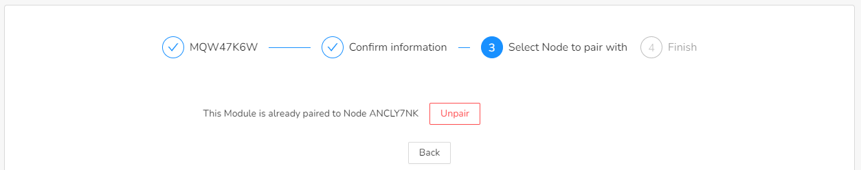
- If a module has already been paired with a Node, You will be offered the possibility of unpairing it.
- If a module has already been paired with a Node, You will be offered the possibility of unpairing it.
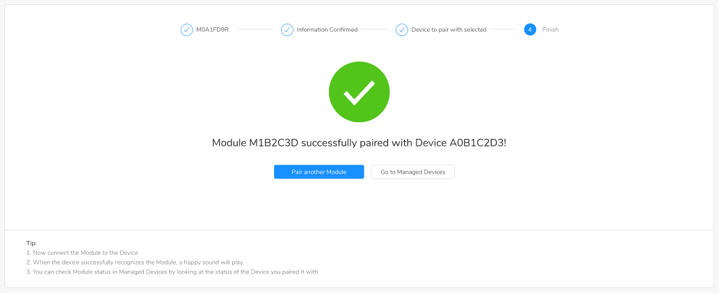
- You will see a message indicating that device pairing was successful. Continue to assemble and deploy the module. If you see any errors, contact support@clarity.io for help.

Physically connect Module to the Clarity Node-S
Tip: We recommend performing a test connection before deployment in the field to ensure data is being uploaded to Clarity Dashboard. There is no need to unconfigure before moving, just remove power and cables and you’re ready to transport.
⚠️ Every time the Black Carbon Module is power cycled, the Filter Tape Cartridge is advanced by one spot. Please minimize the number of power cycles to minimize tape waste.- Assemble and configure the Clarity Node-S in the Clarity Dashboard that will be paired with the Black Carbon module. Please review the Clarity Node-S deployment guide here.
- Note: The Black Carbon module requires the Clarity Node-S be externally powered so the small node-mounted solar panel is not needed.
- Connect the Black Carbon module to the Clarity Node-S by plugging in the accessory cable to the Clarity accessory port as shown below. Twist the cable connector bushing clockwise into the threaded Node connector several turns until finger-tight, do not use a wrench. While you’re at it make sure the adjacent Node antenna connector is also finger-tight and the antenna is pointing vertically.

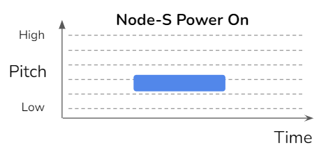
- Once you plug in the Module cable to the Clarity Node-S, a Node-S Power On sound will occur and the device will restart connection to the Clarity Cloud. You can confirm the module has power by observing that the display is lit up and showing information.
- Wait as the Clarity Node-S first establishes cellular connection at your site. This may take anywhere from 2-10 minutes depending on cellular signal strength.
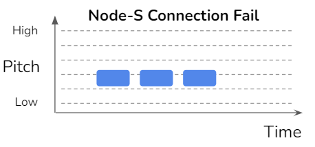
- If the Node-S Connection Failure sound plays, please confirm that the device has been configured on the Dashboard first.
- If no sound plays, the node is not able to connect to the cellular network. Make sure you are in an area with cellular connectivity coverage.
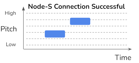
- If the Node-S Connection Successful sound plays, proceed to deploy the device.
- If you are unable to get the node to play the Connection Successful sound, please contact us support@clarity.io.
- If the Node-S Connection Failure sound plays, please confirm that the device has been configured on the Dashboard first.
- After successful connection of the Clarity Node-S, the device will connect with the Module.
- A successful module connection will play a Successful Module Connection sound.
- A failed module connection will play a Failed Module Connection sound. If failed, please check the cable connection between the Clarity Node-S and the Module.
- If you hear the Module Configuration Error sound, the Clarity Node-S is not configured to accept modules. Please ensure you completed the pairing procedure described above.
- If you are not able to get a Successful Module Connection sound, please contact us support@clarity.io.
- After the module is successfully connected, check that data from the Node-S and the Black Carbon module are uploading.
- Login to Clarity Dashboard.
- Navigate to the Analytics > Explore page
- Change the data aggregation to “Highest Resolution” by clicking “Edit” next to Data Loaded. Change the Parameter to Black Carbon > Highest Resolution > Mass Concentration (All Sources)
- In the Map, click on the device connected to the Black Carbon module, then click “Show In Plot”. Once data is uploaded you will see values here.
- Note you will need to manually update the dashboard page as it does not automatically refresh. DO NOT hit your browser’s refresh button, instead load the most recent time period by clicking “Edit” next to Data Loaded.
Note: during the first 30 minutes after starting the Black Carbon Module, it is warming up. Please disregard data from this time period.
Deploy the Node-S + Black Carbon Module in the Field
⚠️ Every time the Black Carbon Module is power cycled, the Filter Tape Cartridge is advanced by one spot. Please minimize the number of power cycles to minimize tape waste.
- Review the Black Carbon Module Siting tips to select a deployment site.
- After the site has been selected, plan the installation of the Clarity Node-S device to the designated pole or other structure.
- To make installation easier, you can temporarily detach the Black Carbon module cable from the node module port.
- Prepare stainless steel zip ties, hose clamps, or screws (not provided).
- Ensure the inlet and outlet will be facing downwards and unobstructed.
- Ensure that the cable will be able to reach the Black Carbon Module once it is installed.
- More instructions on deploying the Clarity Node-S are here.
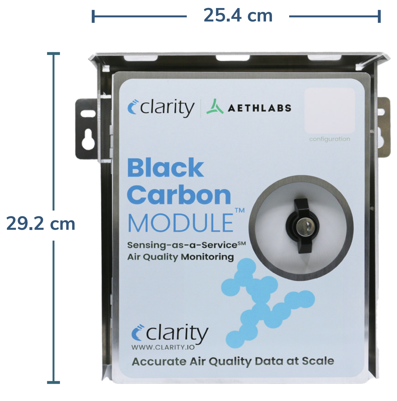
- Mount the Black Carbon Module to the designated pole or panel. Please refer to the dimensions and images below to select proper mounting hardware for the Black Carbon module depending on where you plan to install it.
- Dimensions: 25.4 cm (W) x 29.2 cm (H) x 14.4cm (D). Weight: 11 lbs / 5 kg
- Pole mounting brackets (included) and hose clamps (not included) may be used with the pre-drilled and tapped holes in the back side of the sun shield for vertical or horizontal pole mounting - as shown in the images above. Alternatively the mounting “ears” can be used to attach the module to a flat surface or other bracketry that can properly support the weight.

- Dimensions: 25.4 cm (W) x 29.2 cm (H) x 14.4cm (D). Weight: 11 lbs / 5 kg
- If applicable, plan the installation of the optional Clarity External Power System (EPS)
- Clarity External Power System (EPS) Dimensions:
- Solar Panel: 838.2 mm (W) x 736.6 mm (H) x 25.4 mm (D)
- Battery Enclosure: 533.4 mm (W) x 139.7 mm (H) x 101.6 mm (D)
- Total Weight: 48.5 lbs / 22 kg
- A typical Clarity Node and Black Carbon Module deployment, mounted underneath the optional Clarity External Power System (EPS) is shown below.
- Clarity External Power System (EPS) Dimensions:
- Install the included Inlet Protection Kit - designed to help protect the instrument and data from moderate water and bug intrusion and in-line condensation throughout the sampling train. This kit includes a protection cone, water/bug trap, all necessary tubing and connectors, along with mount and cable ties for installation. Detailed instructions are provided in the next section of this document, a summary is below:
- Connect the water/bug trap to the module’s inlet

- The small black arrow on the bottom of the Module indicates the inlet (see image).
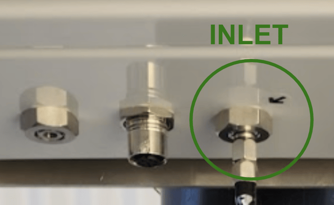
- The large arrow on the front of the bug/water trap indicates the direction or airflow, and therefore should point towards the tube section that plugs into the Black Carbon Module's inlet.
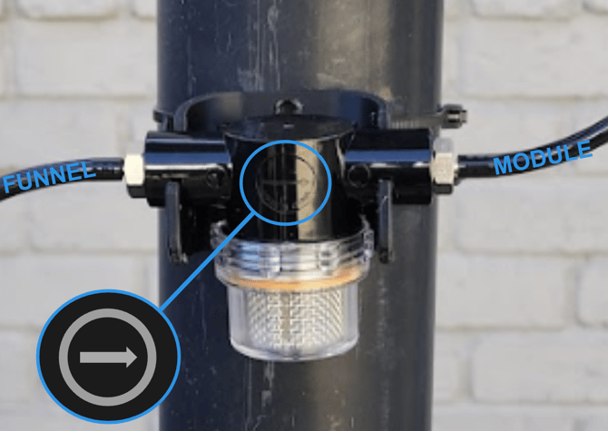
- The small black arrow on the bottom of the Module indicates the inlet (see image).
- Ensure that the funnel is mounted below the Black Carbon module with the water/bug trap in between, so that gravity can drain out water and debris.

- Tubing between all of these should be as short and straight as possible. It is suggested to cut tubes at will to achieve this. When required, bending should be as gentle as possible.
- Connect the water/bug trap to the module’s inlet
- Re-attach the Black Carbon Module cable to the Clarity Node-S after both devices are securely installed
- Listen for the following sounds in succession:

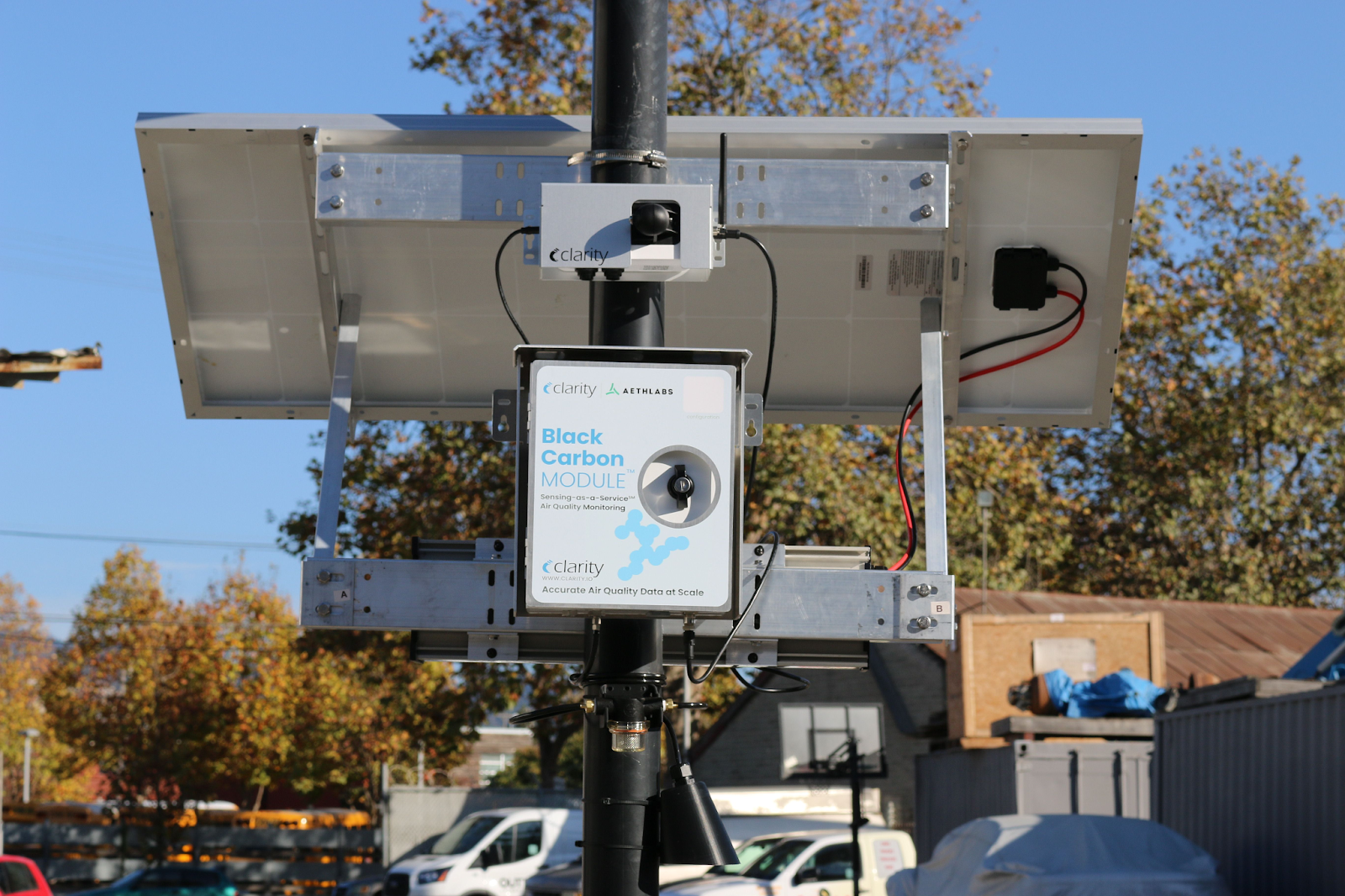
Clarity Node and Black Carbon Module successfully deployed underneath the optional External Power System.
Inlet Protection Kit Details
The Inlet Protection Kit is designed to help protect the BC1 from moderate water/bug intrusion and from in-line condensation throughout the sampling train.
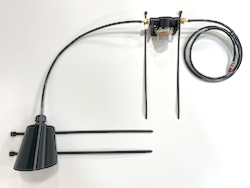
The kit consists of the following items:
-
- 1 (one) protection cone with a compressible gland fitting and 1 18” length of static dissipative tubing installed
- 1 (one) water/bug trap with 2 fittings
- 1 (one) installation mount for water/bug trap
- 4 (one) large cable ties for mount and cone
- 1 (one) 40” length of static dissipative tubing with 1 barb fitting swivel connector installed
Note: To optimize protection of your instrument and data, please read the below installation recommendations:
- Always use the shortest possible tubing lengths.
- Avoid sharp turns in tubing where possible.
- To install the protection cone, insert the tubing into the fitting at the base of the cone so that a small amount (~1 inch) extrudes within the cone interior. Secure the tubing in the compressible gland fitting by rotating the nut on the fitting so it compresses against the tube to form a seal. Do not overtighten. Note: This may be installed already. The large open end of the cone should be pointed facing the ground. The path of air flow from the opening of the cone to the tubing inlet itself should be vertical to the ground or in the orientation that best protects it from moisture such as precipitation or splashing.
- Install the water/bug trap in the sampling train as closely as possible to the instrument itself. We recommend no more than a few inches of tubing separate the instrument inlet from the trap—or as needed to minimize sharp turns within the tube.
- Position the water/bug trap in the sampling train so that the air flow through the trap to the instrument is in the direction of the arrow indicated on the front side of the trap. The water/bug trap is designed for one-way usage.
- Firmly mount the inlet/outlet arms and the base of the water/bug trap so that they are parallel to the ground. Gravity plays an important role and requires that the air flow through the trap arms is parallel to the ground.
- Use the provided custom mount and cable ties for stable, secure installation of the water/bug trap. If using screws in lieu of cable ties for installation, be sure to source appropriate screws and do not overtighten. Be sure not to cinch the cable ties around any of the tubing lengths. After the mount has been installed, clip the trap arms securely into the mount.
- Ensure that the tubing always has at least a slight incline from the tubing inlet to the water/bug trap, and from the trap to the instrument. This orientation of the tubing leverages gravity to provide additional protection against water. Loops, u-shaped depressions or sharp bends in the tubing line should be avoided, as water can accumulate in these areas causing condensed moisture to be drawn into the instrument.